Program do projektowania anten logarytmiczno-periodycznych LPCAD (Log Periodic CAD)
Home
Telekomunikacja
Anteny
Anteny logarytmiczno-periodyczne
LPCAD - Log Periodic CAD
LPCAD 3.56 is now available for Beta testing. This version improves the effect of the 2 director elements that can be added in front of the LPDA in the SAVE:NEC function. This version also adds a new segmentation feature in the SAVE:NEC function. Early versions of LPCAD only allowed the element segmentation to decrease by 2 between adjacent LPDA elements (e.g. 21, 19, 17, 15, 13, 11 segments per element). This results in excessive element segmentation and a very large model for LPDA's with more than 15 elements. Recently, I added constant element segmentation for LPDA's with a TAU of 0.96 or larger. (e.g. 25, 25, 25, ...) Ideally, the element segmentation should scale along with TAU, however this is very difficult to implement. Version 3.56 adds an element segmentation algorithm which changes the segmentation on every other element. This is automatically implemented between TAU 0.90 and TAU 0.96. (e.g. 21, 21, 19, 19, 17, 17, ...) You may download LPCAD version 3.56 here. Please let me know if you find any "bugs".
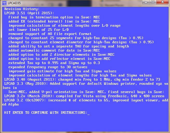
LPCAD 3.53 is the most current released version. Version 3.53 incorporates a bug fix for creating a "known design" and another bug fix which allows LPCAD to exit normally in Windows 10. Please email me at rgcox2 (at) gmail.com if you find any bugs or to suggest improvements. You may download LPCAD35.zip here. LPCAD35.zip contains LPCAD35.EXE which was created on Jan. 7, 2016 at 9:01am and has a size of 262KB (268,800 bytes). If your anti-virus blocks the normal download, you may also download LPCAD35.7z, which was created by 7-Zip. This file is password protected. After download, move the 7-Zip file to a folder "excluded" from scan, then unzip using 7-Zip. The password is "logperiodic". You can also download the previous (3.52) version here. Here are the major improvements within LPCAD 3.51, 3.52 and 3.53: A few bugs have been fixed and the EK (extended kernel) line added to files created by Save:NEC. The EK option helps NEC-2 simulations when the segment length to radius value is low and parallel elements are close together. The EK option is not used in NEC-4, so if you use NEC-4, just delete this line in the input file. I have also modified the way LPCAD calculates the first (longest) element in the array by including an algorithm that uses the L/D ratio along with the lowest frequency. In addition, I have removed the Save:AO export file option. It wasn't working correctly, and since no one has complained, I assume that no one uses it anyway. I have also added a branch in the routine that creates the element segmentation in Save: NEC. Designs with Tau greater than 0.95 will cause LPCAD to segment the elements equally (25 segments per element) during the NEC file creation. I am still trying to figure out how to change the segmentation gradually with different values of Tau, but have hit a brick wall so far. In addition to the previous changes, I have also added the capability of adding 2 parasitic director elements in front of the LPDA. These flatten out the gain vs. frequency curve and in some cases add as much as 2 dB gain to the higher frequencies in the passband. There is also the option of adding a single reflector behind the LPDA during the NEC file creation. The most recent changes involve the expansion of TAU to 0.995 and SIGMA to 0.30. The new gain lookup tables for these high values will show the minimum gain across the frequency range specified. The peak gain may be as much as 2 dB higher near the low end of the passband. These high TAU and SIGMA values will also move the passband down slightly from what was entered, so LPCAD calculates new values of F1 and FH based on TAU and SIGMA and use these to calculate the element lengths. The result should be very close to the frequency range desired. Another interesting modification is the ability to set TAU separately for element lengths and spacing. If you are curious, give it a try and see what happens. I am still thinking about a new version of LPCAD for tapered elements in the 3-30 MHz frequency range. It would likely be called LPCAD-HF. After inputing the frequency range, Tau and Sigma parameters, you would need to also choose which type of element taper to use, such as the "Hy-Gain" taper, which is based on the 204BA reflector and good for 100 mph winds using EIA/RS-222-C. Another option would include the "Tennadyne" taper which uses 0.375" OD tips. If you have other suggested taper schedules, please let me know. The output of LPCAD-HF would be NEC file format for either NEC-4 and NEC4/MP or the NEC-4 engine used in 4NEC2. NEC-2 is not suitable for use with tapered elements. It will calculate results, however there is usually a significant frequency offset. There are other functions of NEC-4 that may also get used such as the expanded GM (geometry move) features. Release of any beta version is likely months away. Right now I am looking for features that will be used. Please send me your input if you are interested. I have heard from one person so far. If you still use DOS instead of Windows, you may wish to download this older file: LPCAD33A.zip. I like to use 4NEC2 to evaluate my LPDA models. It is a very nice, full featured version of NEC2. You can find the latest version of 4NEC2 here: http://www.qsl.net/4nec2 You can also find a faster NEC2 "engine" for 4NEC2. The NEC2/MP "engine" will speed up computation tremendously in dual and quad core PC's. A model that took 60 seconds to run in 4NEC2's existing computation engine should complete under 25 seconds using the NEC2/MP engine in a dual core CPU and under 12 seconds in a quad core CPU.
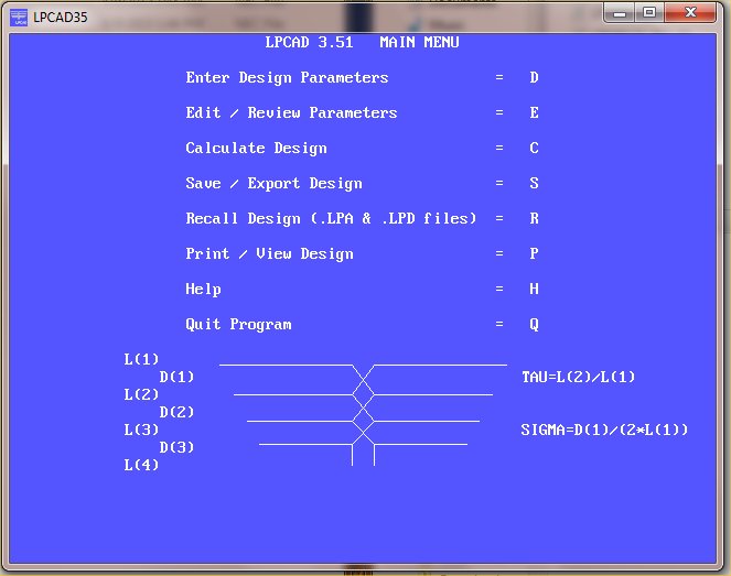
Here are a couple screen shots from LPCAD 3.51 running in Windows 7:
Now I am thinking about version 3.6. Here are things that I am considering:
1. Support for 4NEC2 file format (with variables and special commands) in SAVE:
2. Ability to Save a NEC file with Metric dimensions
3. Ability to create a Loggi design and Save as a NEC file
4. Support for MMANA file format in SAVE:
5. Add mouse support
If you have other suggestions, please email me at rgcox2 (at) gmail.com. Thanks!
Links
Examples of Antennas Designed with LPCAD
Theory of Log Periodic Array Design
How to use LPCAD
Example 1:
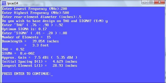
Suppose that I want to design an LPDA to cover the frequencies of 200 - 500 MHz with approximately 7.5 dBi gain and F/B of 23 dB or more. The largest diameter element should be made from 0.5" aluminum tubing or rod.
From the curves in Figure 2, I will initially select Tau = 0.92 and Sigma = 0.08. This should give me approximately 7.5 dBi gain and 22-24 dB F/B. In LPCAD, I use these numbers in "Enter Design Parameters". The LPCAD34 screen should look like that below.
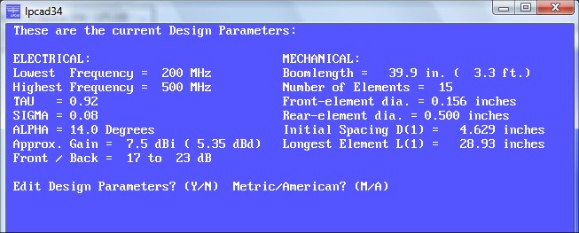
When I select "Edit / Review Parameters" after entering the above data, I see this screen below.
This might be a little low for the 22-24 dB F/B that I wanted, but lets continue to see what this design gives. The boomlength of about 40 inches (1 meter) is OK and the smallest element diameter of 0.156 inch is also OK. For actual construction, I will likely round the element diameters to something commonly available such as 0.125", 0.1875", 0.25", etc.
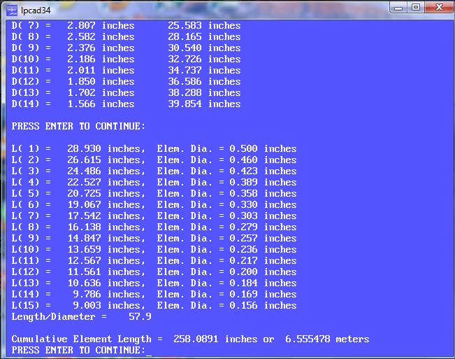
Next, press "N" to return to the Main Menu, then press "C" for "Calculate Design". LPCAD calculates the element lengths and spacings and gives the L/d ratio as 57.9. The screen should look like the one below.
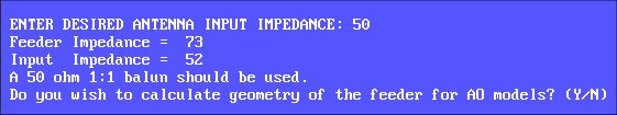
Press "Enter" to continue. LPCAD will ask you what input impedance is wanted, then after you enter the value, it will get as close as possible. The feeder "Z" lower limit is set at 73 ohms, which along with the elements, determines the input "Z". See the screen shot below. Unless you use K6STI's AO (Antenna Optimizer) program, you can normally ignore the question about calculating the geometry of the feeder. NEC (4NEC2, GNEC, etc.) gives you the TL (transmission line) parameter, which is very easy to use. If you Save/Export the design to the NEC format, this will be used automatically.
Press "N" to return to the Main Menu. At this point, if you are satified with the design, you can save it in 3 ways. Press "S" to go to the "Save/Export" menu. Press "D" to save the design in the LPCAD format. You can later recall this file to edit or review the design. You can also save in the K6STI AO format if you happen to use this software. The most popular file format to save to is NEC - Numerical Electromagnetics Code. Press "N" to save to this format. LPCAD will then ask you some questions during the SAVE-NEC process.
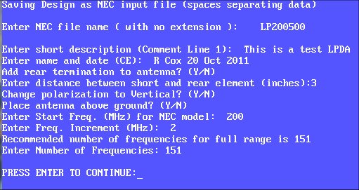
In the screenshot above, I typed in "LP200500" as the file name. The extension "NEC" will be added automatically. I like to use the beginning and ending frequencies as part of the filename, however you can use any naming convention that you want. The description, name and date are also just suggestions for the first 2 comment lines of the Nec file. I would recommend adding a rear termination to all LPDA designs. This is a short circuit at the end of a short transmission line at the rear end of the LP. This termination helps, but does not completely eliminate the narrow-band VSWR spikes that are normally found in the frequency swept response. At each of these "spikes" the F/B and gain also degrade. The best way to minimize these "spikes" is to use a TAU of 0.93 or higher along with a rear termination.
Other options in the SAVE-NEC option include changing the polarity from horizontal to vertical, placing the antenna above ground, and entering the start frequency and frequency step size. In 4NEC2, you can override these frequency settings by choosing the Frequency Sweep option. Once you see the "Press Enter to Continue" line, the NEC input file has been saved in the current folder (where LPCAD is located). I like to place the LPCAD.exe file in the model folder of 4NEC2, so I can easily find the NEC files when I use 4NEC2.
Example 1 - 4NEC2 Analysis
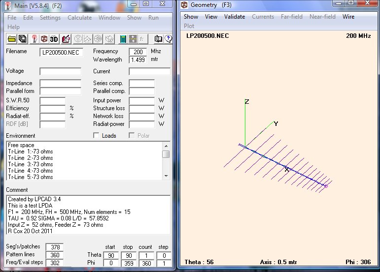
On page 1, I created and saved the NEC file "LP200500". After you start 4NEC2, go to the "File" menu to find and open the LP200500.nec file. This is what you should see after opening the file for the first time.
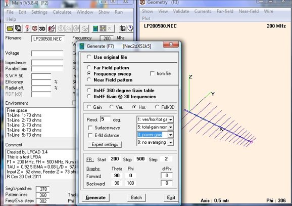
Select "Calculate" from the 4NEC2 menu bar, then select "NEC Output Data". You should see something similar to the screenshot below. Select "Frequency Sweep", "Hor.", "0:Power Gain", Start 200, Stop 500, Step 2, Theta Forward 90, Theta Backward -90, then press "Generate".
After you press "Generate", 4NEC2 opens the input file and begins the calculations. Your screen should look similar to the one below until done.
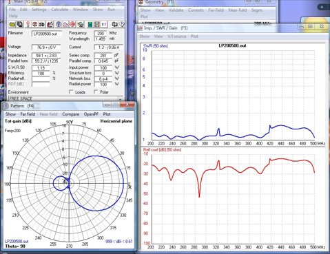
After the calculations are done, you should see this display:
In the VSWR sweep, you can see 2 very sharp "spikes", one near 320 MHz and another near 420 MHz. These are anomolous resonances that come from the impedance of the rear short transformed through 1/2 wavelength of the feeder to the approximate location of the active elements at these frequencies.
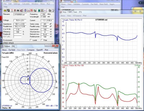
Below, you can view the Gain and F/B sweeps of this antenna.
You can notice that these "spikes" also occur in the gain and F/B at roughly the same frequencies. The pattern shown on the left shows the increased backlobe at 324 MHz, near one of the "spikes". For most Ham uses, these "spikes" can be moved to frequencies where they don't cause any problems. To move the spikes, move the location of the rear termination - closer to the rear element moves the "spikes" higher in frequency - farther away from the rear element moves them lower. If your application requires no "spikes" or very minimal change in gain & F/B, then you should redesign the LP by using a Tau of 0.93 or higher.
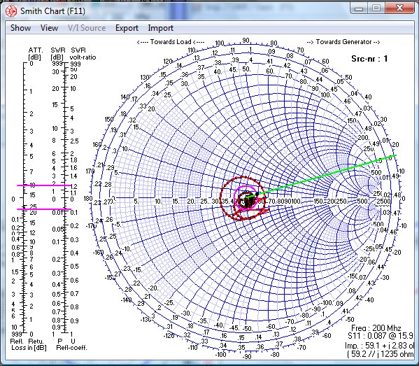
Here is the Smith Chart display for this antenna. Notice that the impedance nicely circles around 50 ohms!
Home
Telekomunikacja
Anteny
Anteny logarytmiczno-periodyczne
© 2000-2023 EJK. All rights reserved. Jerzy Kazojć.